Aileron
.png)
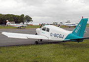
Ailerons are hinged control surfaces attached to the trailing edge of the wing of a fixed-wing aircraft. The ailerons are used to control the aircraft in roll. The two ailerons are typically interconnected so that one goes down when the other goes up: the downgoing aileron increases the lift on its wing while the upgoing aileron reduces the lift on its wing, producing a rolling moment about the aircraft's longitudinal axis.[1] The word aileron is French for "little wing".
An unwanted side effect of aileron operation is adverse yaw—a yawing moment in the opposite direction to the roll. Using the ailerons to roll an aircraft to the right produces a yawing motion to the left. As the aircraft rolls, adverse yaw is caused primarily by the change in drag on the left and right wing. The rising wing generates increased lift which causes increased induced drag. The descending wing generates reduced lift which causes reduced induced drag. The difference in drag on each wing produces the adverse yaw. There is also often an additional adverse yaw contribution from a difference in profile drag between the up-aileron and down-aileron.
Adverse yaw is effectively compensated by the use of the rudder, which results in a sideforce on the vertical tail which opposes the adverse yaw by creating a favorable yawing moment. Another method of compensation is differential ailerons, which have been rigged such that the downgoing aileron deflects less than the upgoing one. In this case the opposing yaw moment is generated by a difference in profile drag between the left and right wingtips. Frise ailerons accentuate this profile drag imbalance by protruding beneath the wing of an upward-deflected aileron, most often by being hinged slightly behind the leading edge and near the bottom of the surface, with the lower section of the leading edge protruding slightly below the wing's undersurface when the aileron is deflected upwards, substantially increasing profile drag on that side. Ailerons may also be designed to use a combination of these methods.[1]
With ailerons in the neutral position the wing on the outside of the turn develops more lift than the opposite wing due to the variation in airspeed across the wing span, and this tends to cause the aircraft to continue to roll. Once the desired angle of bank (degree of rotation on the longitudinal axis) is obtained, the pilot uses opposite aileron to prevent the angle of bank from increasing due to this variation in lift across the wing span. This minor opposite use of the control must be maintained throughout the turn. The pilot also uses a slight amount of rudder in the same direction as the turn to counteract adverse yaw and to produce a "coordinated" turn where the fuselage is parallel to the flight path. A simple gauge on the instrument panel called the slip indicator, also known as "the ball", indicates when this coordination is achieved.[1]
Contents |
History
Since the need for roll control on aircraft was not as obvious as the need for heading and pitch control, the aileron came into widespread use well after the rudder and elevator. The Wright Brothers used wing warping instead of ailerons for roll control, and initially, their aircraft had much better control in the air than aircraft that used movable surfaces; however, as aileron designs were refined, and aircraft became larger and heavier, it became clear that they were much more effective and practical for most aircraft.
There are conflicting claims over who first invented the aileron. In 1868, before the advent of powered aircraft, English inventor M.P.W. Bolton patented the first aileron-type device for lateral control.[2] New Zealander Richard Pearse may have made a powered flight in a monoplane that included small ailerons as early as 1902, but his claims are controversial (and sometimes inconsistent), and even by his own reports, his aircraft were not well controlled. The aircraft 14 Bis by Santos Dumont was modified to add ailerons in late 1906, though it was never fully controllable in flight, likely due to its unconventional wing form. Ailerons were also developed independently by the Aerial Experiment Association, headed by Alexander Graham Bell and by Robert Esnault-Pelterie, a French aircraft builder. Henry Farman's ailerons on the Farman III were the first to resemble ailerons on modern aircraft, and have a reasonable claim as the ancestor of the modern aileron.[2] Other claimants include American William Whitney Christmas, who claimed to have invented the aileron in the 1914 patent for what would become the Christmas Bullet (built in 1918)[3] and American Glenn Curtiss, who flew an aileron-controlled aircraft in 1908. Curtiss had previously been a member of Bell's Aerial Experiential Association, which had the developed ailerons for their aircraft. The AEA members were later dismayed when Curtiss dropped out of their organization, patented their innovation and sold the patent to the United States Government.
Aileron spades
These are flat metal plates, usually attached to the aileron lower surface, ahead of the aileron hinge, by a lever arm. They reduce the force needed by the pilot to deflect the aileron and are often seen on aerobatic aircraft. As the aileron is deflected upward, the spade produces a downward aerodynamic force, which tends to rotate the whole assembly so as to further deflect the aileron upward. The size of the spade (and its lever arm) determine how much force the pilot needs to apply to deflect the aileron.
Aileron balance weights
To prevent control surface flutter (aeroelastic flutter), the center of lift of the control surface should be behind the center of gravity of that surface. To achieve this, lead weights may be added to the front of the aileron. In some aircraft the aileron construction may be too heavy to allow this system to work without huge weight increases. In this case, the weight may be added to a lever arm to move the weight well out in front to the aileron body. These balance weights are tear drop shapes (to reduce drag) which make them appear quite different from spades, although both project forward and below the aileron.
Types of ailerons
Frise Ailerons
Engineer Leslie George Frise (1897–1979) developed an aileron shape which is often used due to its ability to counteract adverse yaw. The Frise aileron is pivoted at about its 25 to 30% chord line and near its bottom surface. When the aileron is deflected up (to make its wing go down), the leading edge of the aileron dips into the airflow beneath the wing. The moment of the leading edge in the airflow helps to move up the trailing edge, decreasing the stick force. The down-moving aileron also adds energy to the boundary layer by the airflow from the under-side of the wing that scoops air by the edge of the aileron that follows the upper surface of the aileron and creates a lifting force on the upper surface of the aileron aiding the lift of the wing. That reduces the needed deflection angle of the aileron. If the leading edge of the aileron is sharp or bluntly rounded, that adds significant drag to that wing and help the aircraft to yaw (turn) in the desired direction, but adds some unpleasant or potentially dangerous aerodynamic vibration (flutter).
Differential ailerons
By careful design of the mechanical linkages, the up aileron can be made to deflect more than the down aileron (e.g.[4]). This helps reduce the likelihood of a wing tip stall when aileron deflections are made at high angles of attack. The idea is that the loss of lift associated with the up aileron carries no penalty while the increase in lift associated with the down aileron is minimized. The rolling couple on the aircraft is always the difference in lift between the two wings.
The de Havilland Tiger Moth classic British biplane is one of the best-known aircraft, and one of the earliest, to use differential ailerons.
Combination with other control surfaces
- A control surface that combines an aileron and flap is called a flaperon. A single surface on each wing serves both purposes: used as an aileron, the flaperons left and right are actuated differentially; when used as a flap, both flaperons are actuated downwards. When a flaperon is actuated downwards (i.e. used as a flap) there is enough freedom of movement left to be able to still use the aileron function.
- A further form of roll control, common on modern jet transport aircraft, utilises spoilers in conjunction with ailerons. This is called a spoileron.
- In a delta-winged aircraft, the ailerons are combined with the elevators to form an elevon.
- Several modern fighter aircraft may have no ailerons on the wings at all, and combine roll control with an all-moving tailplane. This is a taileron or a rolling tail.
See also
- Aircraft flight control system
- Trailing edge
- Flaperon
References
- ↑ 1.0 1.1 1.2 Kermode, A.C. (1972), Mechanics of Flight, Chapter 9 (8th edition), Pitman Publishing Limited, London. ISBN 0 273 31623 0
- ↑ 2.0 2.1 Aerospaceweb
- ↑ Aerospaceweb
- ↑ United States Patent 1565097, Mummert 1925 http://www.freepatentsonline.com/1565097.pdf
External links
- NASA Glenn Research Center aileron article with Java demo and more pictures
|
||||||||||||||||||||||||||
|
||||||||||||||