Buckling
| Materials failure modes |
|---|
| Buckling |
| Corrosion |
| Creep |
| Fatigue |
| Fracture |
| Impact |
| Mechanical overload |
| Thermal shock |
| Wear |
| Yielding |
In engineering, buckling is a failure mode characterized by a sudden failure of a structural member subjected to high compressive stresses, where the actual compressive stress at the point of failure is less than the ultimate compressive stresses that the material is capable of withstanding. This mode of failure is also described as failure due to elastic instability. Mathematical analysis of buckling makes use of an axial load eccentricity that introduces a moment, which does not form part of the primary forces to which the member is subjected.
Contents |
Columns

The ratio of the effective length of a column to the least radius of gyration of its cross section is called the slenderness ratio (sometimes expressed with the Greek letter lambda, λ). This ratio affords a means of classifying columns. All the following are approximate values used for convenience.
- A short steel column is one whose slenderness ratio does not exceed 50; an intermediate length steel column has a slenderness ratio ranging from about 50 to 200, while a long steel column may be assumed to have a slenderness ratio greater than 200.
- A short concrete column is one having a ratio of unsupported length to least dimension of the cross section not greater than 10. If the ratio is greater than 10, it is a long column (sometimes referred to as a slender column).
- Timber columns may be classified as short columns if the ratio of the length to least dimension of the cross section is equal to or less than 10. The dividing line between intermediate and long timber columns cannot be readily evaluated. One way of defining the lower limit of long timber columns would be to set it as the smallest value of the ratio of length to least cross sectional area that would just exceed a certain constant K of the material. Since K depends on the modulus of elasticity and the allowable compressive stress parallel to the grain, it can be seen that this arbitrary limit would vary with the species of the timber. The value of K is given in most structural handbooks.
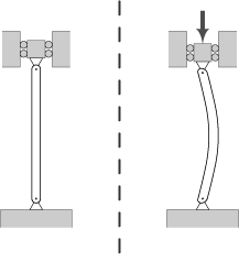
If the load on a column is applied through the center of gravity of its cross section, it is called an axial load. A load at any other point in the cross section is known as an eccentric load. A short column under the action of an axial load will fail by direct compression before it buckles, but a long column loaded in the same manner will fail by buckling (bending), the buckling effect being so large that the effect of the direct load may be neglected. The intermediate-length column will fail by a combination of direct compressive stress and bending.
In 1757, mathematician Leonhard Euler derived a formula that gives the maximum axial load that a long, slender, ideal column can carry without buckling. An ideal column is one that is perfectly straight, homogeneous, and free from initial stress. The maximum load, sometimes called the critical load, causes the column to be in a state of unstable equilibrium; that is, any increase in the load, or the introduction of the slightest lateral force, will cause the column to fail by buckling. The formula derived by Euler for columns with no consideration for lateral forces is given below. However, if lateral forces are taken into consideration the value of critical load remains approximately same.
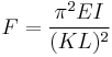
where
 = maximum or critical force (vertical load on column),
 = modulus of elasticity,
 = area moment of inertia,
 = unsupported length of column,
 = column effective length factor, whose value depends on the conditions of end support of the column, as follows.
- For both ends pinned (hinged, free to rotate), = 1.0.
- For both ends fixed, = 0.50.
- For one end fixed and the other end pinned, = 0.699....
- For one end fixed and the other end free to move laterally, = 2.0.
- For both ends pinned (hinged, free to rotate),
Examination of this formula reveals the following interesting facts with regard to the load-bearing ability of slender columns.
- Elasticity and not compressive strength of the materials of the column determines the critical load.
- The critical load is directly proportional to the second moment of area of the cross section.
- The boundary conditions have a considerable effect on the critical load of slender columns. The boundary conditions determine the mode of bending and the distance between inflection points on the deflected column. The closer together the inflection points are, the higher the resulting capacity of the column.
The strength of a column may therefore be increased by distributing the material so as to increase the moment of inertia. This can be done without increasing the weight of the column by distributing the material as far from the principal axes of the cross section as possible, while keeping the material thick enough to prevent local buckling. This bears out the well-known fact that a tubular section is much more efficient than a solid section for column service.
Another bit of information that may be gleaned from this equation is the effect of length on critical load. For a given size column, doubling the unsupported length quarters the allowable load. The restraint offered by the end connections of a column also affects the critical load. If the connections are perfectly rigid, the critical load will be four times that for a similar column where there is no resistance to rotation (hinged at the ends).
Since the moment of inertia of a surface is its area multiplied by the square of a length called the radius of gyration, the above formula may be rearranged as follows. Using the Euler formula for hinged ends, and substituting A·r2 for I, the following formula results.
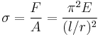
where  is the allowable stress of the column, and
  is the slenderness ratio.
Since structural columns are commonly of intermediate length, and it is impossible to obtain an ideal column, the Euler formula on its own has little practical application for ordinary design. Issues that cause deviation from the pure Euler strut behaviour include imperfections in geometry in combination with plasticity/non-linear stress strain behaviour of the column's material. Consequently, a number of empirical column formulae have been developed to agree with test data, all of which embody the slenderness ratio. For design, appropriate safety factors are introduced into these formulae.
Self-buckling
A free-standing, vertical column, with density  , Young's modulus , and radius
  , will buckle under its own weight if its height exceeds a certain critical height:[1][2][3]
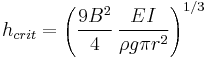
where g is the acceleration due to gravity, I is the second moment of area of the beam cross section, and B is the first zero of the Bessel function of the first kind of order -1/3, which is equal to 1.86635...
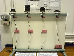
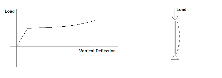
Limit Point vs Bifurcation Buckling[4][5]
Bifurcation buckling is sometimes called Euler buckling even when applied to structures other than Euler columns. As the applied load in increased by a small amount beyond the critical load, the structure deforms into a buckled configuration which is adjacent to the original configuration. For example, the Euler column pictured will start to bow when loaded slightly above its critical load, but won't suddenly collapse.
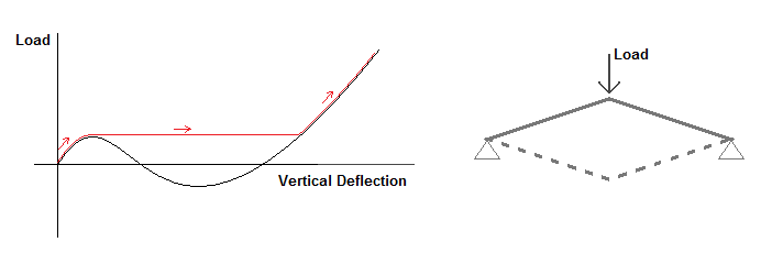
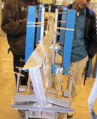
In structures experiencing limit point instability, if the load is increased infinitesimally beyond the critical load, the structure undergoes a large deformation into a different stable configuration which is not adjacent to the original configuration. An example of this type of buckling is a toggle frame (pictured) which 'snaps' into its buckled configuration.
Bicycle wheels
A conventional bicycle wheel consists of a thin rim kept under high compressive stress by the (roughly normal) inward pull of a large number of spokes. It can be considered as a loaded column that has been bent into a circle. As such, if spoke tension is increased beyond a safe level, the wheel spontaneously fails into a characteristic saddle shape (sometimes called a "taco" or a "pringle") like a three-dimensional Euler column. This is normally a purely elastic deformation and the rim will resume its proper plane shape if spoke tension is reduced slightly.
Surface materials

Buckling is also a failure mode in pavement materials, primarily with concrete, since asphalt is more flexible. Radiant heat from the sun is absorbed in the road surface, causing it to expand, forcing adjacent pieces to push against each other. If the stress is great enough, the pavement can lift up and crack without warning. Going over a buckled section can be very jarring to automobile drivers, described as running over a speed hump at highway speeds.
Similarly, rail tracks also expand when heated, and can fail by buckling, see sun kink. It is more common for rails to move laterally, often pulling the underlain railroad ties (sleepers) along .
Energy method
Often it is very difficult to determine the exact buckling load in complex structures using the Euler formula, due to the difficulty in deciding the constant K. Therefore, maximum buckling load often is approximated using energy conservation. This way of deciding maximum buckling load is often referred to as the energy method in structural analysis.
The first step in this method is to suggest a displacement function. This function must satisfy the most important boundary conditions, such as displacement and rotation. The more accurate the displacement function, the more accurate the result.
In this method, there are two equations used to calculate the inner energy and outer energy.
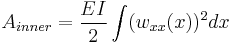
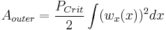
where  is the displacement function and the subscripts "x" and "xx" refer to the first and second derivatives of the displacement. Energy conservation yields:

Lateral-torsional buckling
When a simple beam is loaded in flexure, the top side is in compression, and the bottom side is in tension. If the beam is not supported in the lateral direction (i.e., perpendicular to the plane of bending), and the flexural load increases to a critical limit, the beam will fail due to lateral buckling of the compression flange. In wide-flange sections, if the compression flange buckles laterally, the cross section will also twist in torsion, resulting in a failure mode known as lateral-torsional buckling.
Plastic buckling
Buckling will generally occur slightly before the theoretical buckling strength of a structure, due to plasticity of the material. When the compressive load is near buckling, the structure will bow significantly and approach yield. The stress-strain behaviour of materials is not strictly linear even below yield, and the modulus of elasticity decreases as stress increases, with more rapid change near yield. This lower rigidity reduces the buckling strength of the structure and causes premature buckling. This is the opposite effect of the plastic bending in beams, which causes late failure relative to the Euler-Bernoulli beam equation.
Dynamic buckling
If the load on the column is applied suddenly and then released, the column can sustain a load much higher than its static (slowly applied) buckling load. This can happen in a long, unsupported column (rod) used as a drop hammer. The duration of compression at the impact end is the time required for a stress wave to travel up the rod to the other (free) end and back down as a relief wave. Maximum buckling occurs near the impact end at a wavelength much shorter than the length of the rod, at a stress many times the buckling stress if the rod were a statically-loaded column. The critical condition for buckling amplitude to remain less than about 25 times the effective rod straightness imperfection at the buckle wavelength is

where  is the impact stress, is the length of the rod,
  is the elastic wave speed, and
  is the smaller lateral dimension of a rectangular rod. Because the buckle wavelength depends only on and , this same formula holds for thin cylindrical shells of thickness .[6] The complete theory and example experimental results for long columns are available as a 39-page PDF document at http://lindberglce.com/tech/buklbook.htm
See also
- Compressive stress
- Euler-Bernoulli beam equation
- Sun kink
- Gordon-Rankine
References
- ↑ Kato, K. (1915). "Mathematical Investigation on the Mechanical Problems of Transmission Line". Journal of the Japan Society of Mechanical Engineers 19: 41.
- ↑ Ratzersdorfer, Julius (1936). Die Knickfestigkeit von Stäben und Stabwerken. Wein, Austria: J. Springer. pp. 107–109.
- ↑ Cox, Steven J.; C. Maeve McCarthy (1998). "The Shape of the Tallest Column". Society for Industrial and Applied Mathematics 29: 547–554.
- ↑ "Buckling of Bars, Plates, and Shells" By Robert M. Jones
- ↑ "Observations on eigenvalue buckling analysis within a finite element context" by Christopher J. Earls
- ↑ Lindberg, H. E., and Florence, A. L., Dynamic Pulse Buckling, Martinus Nijhoff Publishers, 1987, pp. 11-56, 297-298.
- Timoshenko, S. P., and Gere, J. M., Theory of Elastic Stability, 2 ed., McGraw-Hill, 1961.
- Nenezich, M., Thermoplastic Continuum Mechanics, Journal of Aerospace Structures, Vol. 4, 2004.
- The Stability of Elastic Equilibrium by W. T. Koiter, PhD Thesis, 1945.