Inductor
| Inductor | |
|---|---|
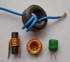 A selection of low-value inductors |
|
| Type | Passive |
| Working principle | Electromagnetic induction |
| First production | Michael Faraday (1831) |
| Electronic symbol | |
An inductor or a reactor is a passive electrical component that can store energy in a magnetic field created by the electric current passing through it. An inductor's ability to store magnetic energy is measured by its inductance, in units of henries. Typically an inductor is a conducting wire shaped as a coil, the loops helping to create a strong magnetic field inside the coil due to Ampere's Law. Due to the time-varying magnetic field inside the coil, a voltage is induced, according to Faraday's law of electromagnetic induction, which by Lenz's Law opposes the change in current that created it. Inductors are one of the basic electronic components used in electronics where current and voltage change with time, due to the ability of inductors to delay and reshape alternating currents. In everyday speak inductors are sometimes called chokes, but this refers to only a particular type and purpose of inductor.
Contents |
Overview
Inductance (L) results from the magnetic field that forms around a current-carrying conductor which tends to resist changes in the current. Electric current through the conductor creates a magnetic flux proportional to the current, and a change in this current creates a corresponding change in magnetic flux which, in turn, by Faraday's Law generates an electromotive force (EMF) that opposes this change in current. Inductance is a measure of the amount of EMF generated per unit change in current. For example, an inductor with an inductance of 1 [Henry (unit)|henry]] produces an EMF of 1 volt when the current through the inductor changes at the rate of 1 ampere per second. The number of loops, the size of each loop, and the material it is wrapped around all affect the inductance. For example, the magnetic flux linking these turns can be increased by coiling the conductor around a material with a high permeability such as iron. This can increase the inductance by 2000 times.
Ideal and real inductors
An "ideal inductor" has inductance, but no resistance or capacitance, and does not dissipate or radiate energy. A real inductor may be partially modeled by a combination of inductance, resistance (due to the resistance of the wire and losses in core material), and capacitance. At some frequency, some real inductors behave as resonant circuits (due to their self capacitance). At some frequency the capacitive component of impedance becomes dominant. Energy is dissipated by the resistance of the wire, and by any losses in the magnetic core due to hysteresis. Practical iron-core inductors at high currents show gradual departure from ideal behavior due to nonlinearity caused by magnetic saturation. At higher frequencies, resistance and resistive losses in inductors grow due to skin effect in the inductor's winding wires. Core losses also contribute to inductor losses at higher frequencies. Practical inductors work as antennas, radiating a part of energy processed into surrounding space and circuits, and accepting electromagnetic emissions from other circuits, taking part in electromagnetic interference. Circuits and materials close to the inductor will have near-field coupling to the inductor's magnetic field, which may cause additional energy loss. Real-world inductor applications may consider the parasitic parameters as important as the inductance.
Applications
Inductors are used extensively in analog circuits and signal processing. Inductors in conjunction with capacitors and other components form tuned circuits which can emphasize or filter out specific signal frequencies. Applications range from the use of large inductors in power supplies, which in conjunction with filter capacitors remove residual hums known as the Mains hum or other fluctuations from the direct current output, to the small inductance of the ferrite bead or torus installed around a cable to prevent radio frequency interference from being transmitted down the wire. Smaller inductor/capacitor combinations provide tuned circuits used in radio reception and broadcasting, for instance.
Two (or more) inductors which have coupled magnetic flux form a transformer, which is a fundamental component of every electric utility power grid. The efficiency of a transformer may decrease as the frequency increases due to eddy currents in the core material and skin effect on the windings. Size of the core can be decreased at higher frequencies and, for this reason, aircraft use 400 hertz alternating current rather than the usual 50 or 60 hertz, allowing a great saving in weight from the use of smaller transformers[1].
An inductor is used as the energy storage device in some switched-mode power supplies. The inductor is energized for a specific fraction of the regulator's switching frequency, and de-energized for the remainder of the cycle. This energy transfer ratio determines the input-voltage to output-voltage ratio. This XL is used in complement with an active semiconductor device to maintain very accurate voltage control.
Inductors are also employed in electrical transmission systems, where they are used to depress voltages from lightning strikes and to limit switching currents and fault current. In this field, they are more commonly referred to as reactors.
Larger value inductors may be simulated by use of gyrator circuits.
Inductor construction
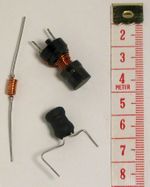
An inductor is usually constructed as a coil of conducting material, typically copper wire, wrapped around a core either of air or of ferromagnetic or ferrimagnetic material. Core materials with a higher permeability than air increase the magnetic field and confine it closely to the inductor, thereby increasing the inductance. Low frequency inductors are constructed like transformers, with cores of electrical steel laminated to prevent eddy currents. 'Soft' ferrites are widely used for cores above audio frequencies, since they don't cause the large energy losses at high frequencies that ordinary iron alloys do. Inductors come in many shapes. Most are constructed as enamel coated wire wrapped around a ferrite bobbin with wire exposed on the outside, while some enclose the wire completely in ferrite and are called "shielded". Some inductors have an adjustable core, which enables changing of the inductance. Inductors used to block very high frequencies are sometimes made by stringing a ferrite cylinder or bead on a wire.
Small inductors can be etched directly onto a printed circuit board by laying out the trace in a spiral pattern. Some such planar inductors use a planar core.
Small value inductors can also be built on integrated circuits using the same processes that are used to make transistors. Aluminium interconnect is typically used, laid out in a spiral coil pattern. However, the small dimensions limit the inductance, and it is far more common to use a circuit called a "gyrator" which uses a capacitor and active components to behave similarly to an inductor.
Types of inductors
Air core coil
The term air core coil describes an inductor that does not use a magnetic core made of a ferromagnetic material. The term refers to coils wound on plastic, ceramic, or other nonmagnetic forms, as well as those that actually have air inside the windings. Air core coils have lower inductance than ferromagnetic core coils, but are often used at high frequencies because they are free from energy losses called core losses that occur in ferromagnetic cores, which increase with frequency. A side effect that can occur in air core coils in which the winding is not rigidly supported on a form is 'microphony': mechanical vibration of the windings can cause variations in the inductance.
Radio frequency inductors
At high frequencies, particularly radio frequencies (RF), inductors have higher resistance and other losses. In addition to causing power loss, in resonant circuits this can reduce the Q factor of the circuit, broadening the bandwidth. In RF inductors, which are mostly air core types, specialized construction techniques are used to minimize these losses. The losses are due to these effects:
- Skin effect: The resistance of a wire to high frequency current is higher than its resistance to DC current because of skin effect. Radio frequency alternating current doesn't penetrate far into the body of a conductor but travels along its surface. So in a solid wire most of the cross sectional area of the wire is not used to conduct the current, which flows in a narrow annulus on the surface. This effect increases the resistance of the wire in the coil, which may already have a relatively high resistance due to its length and small diameter.
- Proximity effect: Another similar effect which also increases the resistance of the wire at high frequencies is proximity effect, which occurs in parallel wires that lie close to each other. The individual magnetic field of adjacent turns induces eddy currents in the wire of the coil, which causes the current in the conductor to be concentrated in a thin strip on the side near the adjacent wire. Like skin effect, this reduces the effective cross sectional area of the wire conducting current, increasing its resistance.
- Parasitic capacitance: The capacitance between individual wire turns of the coil, called parasitic capacitance, doesn't cause energy losses but can change the behavior of the coil. Each turn of the coil is at a slightly different potential, so the electric field between neighboring turns stores charge on the wire. So the coil acts as if it has a capacitor in parallel with it. At a high enough frequency this capacitance can resonate with the inductance of the coil forming a tuned circuit, causing the coil to become self-resonant.
To reduce parasitic capacitance and proximity effect, RF coils are constructed to avoid having many turns lying close together, parallel to one another. The windings of RF coils are often limited to a single layer, and the turns are spaced apart. To reduce resistance due to skin effect, in high power inductors such as those used in transmitters the windings are sometimes made of a metal strip or tubing, and silver-plated.
- Honeycomb coils: To reduce all of the above effects, multilayer RF coils are wound in patterns in which successive turns are not parallel but crisscrossed at an angle; these are often called honeycomb or basket-weave coils.
- Spiderweb coils: Another construction technique with similar advantages is flat spiral coils. These are often wound on a flat insulating support with radial spokes or slots, with the wire weaving in and out through the slots; these are called spiderweb coils. The form has an odd number of slots, so successive turns of the spiral lay on opposite sides of the form, increasing separation.
- Litz wire: To reduce skin effect losses, some coils are wound with a special type of radio frequency wire called litz wire. Instead of a single solid conductor, litz wire consists of several smaller wire strands that carry the current. Unlike ordinary stranded wire, the strands are insulated from each other, to prevent skin effect from forcing the current to the surface, and braided together. The braid pattern insures that each wire strand spends the same amount of its length on the outside of the braid, so skin effect distributes the current equally between the strands, resulting in a larger cross sectional conduction area than an equivalent single wire.
Ferromagnetic core coil
Ferromagnetic-core or iron-core inductors use a magnetic core made of a ferromagnetic or ferrimagnetic material such as iron or ferrite to increase the inductance. A magnetic core can increase the inductance of a coil by a factor of several thousand, by increasing the magnetic field due to its higher magnetic permeability. However the magnetic properties of the core material cause several side effects which alter the behavior of the inductor and require special construction:
- Core losses: A time varying current in a ferromagnetic inductor, which causes a time varying magnetic field in its core, causes energy losses in the core material which are dissipated as heat, due to two processes:
- Eddy currents: From Faraday's law of induction, the changing magnetic field can induce circulating loops of electric current in the conductive metal core. The energy in these currents is dissipated as heat in the resistance of the core material. The amount of energy lost increases with the area inside the loop of current.
- Hysteresis: Changing or reversing the magnetic field in the core also causes losses due to the motion of the tiny magnetic domains it is composed of. The energy loss is proportional to the area of the hysteresis loop in the BH graph of the core material. Materials with low coercivity have narrow hysteresis loops and so low hysteresis losses.
- For both of these processes, the energy loss per cycle of AC current is constant, so core losses increase linearly with frequency.
- Nonlinearity: If the current through a ferromagnetic core coil is high enough that the magnetic core saturates, the inductance will not remain constant but will change with the current through the device. This is called nonlinearity and results in distortion of the signal. For example, audio signals can suffer intermodulation distortion in saturated inductors. To prevent this, in linear circuits the current through iron core inductors must be limited below the saturation level. Using a powdered iron core with a distributed air gap allows higher levels of magnetic flux which in turn allows a higher level of DC current to flow through the inductor before it saturates[2].
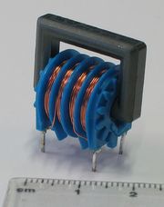
Laminated core inductor
Low frequency inductors are often made with laminated cores to prevent eddy currents, using construction similar to transformers. The core is made of stacks of thin steel sheets or laminations oriented parallel to the field, with an insulating coating on the surface. The insulation prevents eddy currents from flowing between the sheets, so any remaining currents must flow within the cross sectional area of the individual laminations, reducing the area of the loop and thus the energy loss greatly. The laminations are made of low coercivity silicon steel, to reduce hysteresis losses.
Ferrite core inductor
For higher frequencies, inductors are made with cores of ferrite. Ferrite is a ceramic ferrimagnetic material that is nonconductive, so eddy currents cannot flow within it. The formulation of ferrite is xxFe2O4 where xx represents various metals. For inductor cores soft ferrites are used, which have low coercivity and thus low hysteresis losses. Another similar material is powdered iron cemented with a binder.
Toroidal core coils
In an inductor wound on a straight rod-shaped core, the magnetic field lines emerging from one end of the core must pass through the air to reenter the core at the other end. This reduces the field, because much of the magnetic field path is in air rather than the higher permeability core material. So higher magnetic fields and inductance can be achieved by winding the coil on a toroidal or doughnut shaped ferrite core. The magnetic field lines form closed loops within the doughnut without leaving the core material. Toroidal inductors also have the advantage that since little of the magnetic flux is outside the core, they radiate less electromagnetic interference than straight coils. Toroidal core coils are manufactured of various materials, primarily ferrite, Koom Mu® MPP, powdered iron and laminated cores[3].
Variable Inductor
A variable inductor can be constructed by making one of the terminals of the device a sliding spring contact that can move along the surface of the coil, increasing or decreasing the number of turns of the coil included in the circuit. An alternate construction method is to use a moveable magnetic core, which can be slid in or out of the coil. Moving the core farther into the coil increases the permeability, increasing the inductance. Many inductors used in radio applications (usually less than 100 Mhz) use adjustable cores in order to tune such inductors to their desired value, since manufacturing processes have certain tolerances (inaccuracy).
Core Loss
Core loss calculators[4] can be used to determine the type of inductor required. Using inputs such as input voltage, output voltage, output current, frequency, ambient temperature, and inductance these calculators can predict the losses of the inductors core and AC/DC based on the operating condition of the circuit being used[5].
In electric circuits
The effect of an inductor in a circuit is to oppose changes in current through it by developing a voltage across it proportional to the rate of change of the current. An ideal inductor would offer no resistance to a constant direct current; however, only superconducting inductors have truly zero electrical resistance.
The relationship between the time-varying voltage v(t) across an inductor with inductance L and the time-varying current i(t) passing through it is described by the differential equation:
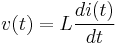
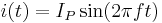
When there is a sinusoidal alternating current (AC) through an inductor, a sinusoidal voltage is induced. The amplitude of the voltage is proportional to the product of the amplitude ( ) of the current and the frequency ( f ) of the current.
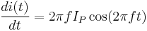
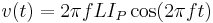
In this situation, the phase of the current lags that of the voltage by π/2.
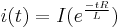
If an inductor is connected to a DC current source, with value I via a resistance, R, and then the current source short circuited, the differential relationship above shows that the current through the inductor will discharge with an exponential decay:
Laplace circuit analysis (s-domain)
When using the Laplace transform in circuit analysis, the impedance of an ideal inductor with no initial current is represented in the s domain by:

-
- where
- L is the inductance, and
- s is the complex frequency.
- where
-
If the inductor does have initial current, it can be represented by:
- adding a voltage source in series with the inductor, having the value:

(Note that the source should have a polarity that is aligned with the initial current)
- or by adding a current source in parallel with the inductor, having the value:

-
- where
- L is the inductance, and
 is the initial current in the inductor.
- where
-
Inductor networks
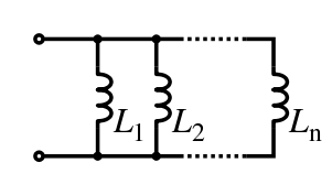
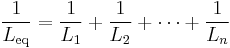
Inductors in a parallel configuration each have the same potential difference (voltage). To find their total equivalent inductance (Leq):
The current through inductors in series stays the same, but the voltage across each inductor can be different. The sum of the potential differences (voltage) is equal to the total voltage. To find their total inductance:
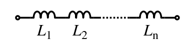
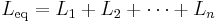
These simple relationships hold true only when there is no mutual coupling of magnetic fields between individual inductors.
Stored energy
The energy (measured in joules, in SI) stored by an inductor is equal to the amount of work required to establish the current through the inductor, and therefore the magnetic field. This is given by:
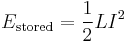
where L is inductance and I is the current through the inductor.
This relationship is only valid for linear (non-saturated) regions of the magnetic flux linkage and current relationship
Q factor
An ideal inductor will be lossless irrespective of the amount of current through the winding. However, typically inductors have winding resistance from the metal wire forming the coils. Since the winding resistance appears as a resistance in series with the inductor, it is often called the series resistance. The inductor's series resistance converts electrical current through the coils into heat, thus causing a loss of inductive quality. The quality factor (or Q) of an inductor is the ratio of its inductive reactance to its resistance at a given frequency, and is a measure of its efficiency. The higher the Q factor of the inductor, the closer it approaches the behavior of an ideal, lossless, inductor.
The Q factor of an inductor can be found through the following formula, where R is its internal electrical resistance and  is capacitive or inductive reactance at resonance:

By using a ferromagnetic core, the inductance is greatly increased for the same amount of copper, multiplying up the Q. Cores however also introduce losses that increase with frequency. A grade of core material is chosen for best results for the frequency band. At VHF or higher frequencies an air core is likely to be used.
Inductors wound around a ferromagnetic core may saturate at high currents, causing a dramatic decrease in inductance (and Q). This phenomenon can be avoided by using a (physically larger) air core inductor. A well designed air core inductor may have a Q of several hundred.
An almost ideal inductor (Q approaching infinity) can be created by immersing a coil made from a superconducting alloy in liquid helium or liquid nitrogen. This supercools the wire, causing its winding resistance to disappear. Because a superconducting inductor is virtually lossless, it can store a large amount of electrical energy within the surrounding magnetic field (see superconducting magnetic energy storage). Bear in mind that for inductors with cores, core losses still exist.
Inductance formulae
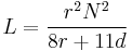
The table below lists some common simplified formulas for calculating the approximate inductance of several inductor constructions.
| Construction | Formula | Dimensions |
|---|---|---|
| Cylindrical air-core coil[6] | 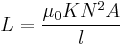 |
|
| Straight wire conductor [7] |  |
|
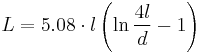 |
|
|
| Short air-core cylindrical coil | 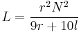 |
|
| Multilayer air-core coil | 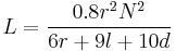 |
|
| Flat spiral air-core coil | 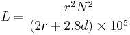 |
|
 |
|
|
| Toroidal core (circular cross-section) | 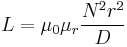 |
|
 × 10−7 H/m
See also
- Capacitor
- Electricity
- Electronic component
- Electronics
- Ferrite bead
- Gyrator
- Inductance (including mutual inductance)
- Induction coil
- Induction cooking
- Induction loop
- RL circuit
- RLC circuit
- Magnetic core
- Magnetomotive force (MMF)
- Memristor
- Reactance (electronics)
- Resistor
- Saturable reactor
- Solenoid
- Transformer
Synonyms
- Choke (electronics)
- coil
- reactor
Notes
- ↑ http://www.wonderquest.com/expounding-aircraft-electrical-systems.htm
- ↑ http://www.newark.com/pdfs/techarticles/vishay/Inductors101.pdf
- ↑ http://www.datasheetarchive.com/datasheet-pdf/072/DSA00379445.html
- ↑ http://www.vishay.com/inductors/calculator-home-list/
- ↑ http://www.element-14.com/community/docs/DOC-17923
- ↑ 6.0 6.1 Nagaoka, Hantaro (1909-05-06). The Inductance Coefficients of Solenoids[1]. 27. Journal of the College of Science, Imperial University, Tokyo, Japan. p. 18.
- ↑ The Self and Mutual Inductances of Linear Conductors, By Edward B. Rosa, Bulletin of the Bureau of Standards, Vol.4, No.2, 1908, p301-344
External links
- General
- How stuff works The initial concept, made very simple
- Capacitance and Inductance - A chapter from an online textbook
- Spiral inductor models. Article on inductor characteristics and modeling.
- Online coil inductance calculator. Online calculator calculates the inductance of conventional and toroidal coils using formulas 3, 4, 5, and 6, above.
- AC circuits
- Understanding coils and transforms